Steel structure load calculation is the foundation of safe, durable, and cost-efficient building design. Whether you are designing a warehouse, factory, or prefabricated PEB structure, understanding how to calculate and combine loads ensures structural stability and compliance with global standards.
This guide explains all key aspects of load design — including types of loads (dead, live, wind, snow, crane, and seismic), load combination principles, and practical design analysis methods using modern tools such as STAADPRO and Tekla. It also covers common challenges in load estimation and software accuracy, along with real-world solutions applied by certified manufacturers.
As a professional steel structure and PEB manufacturer, SteelPRO PEB integrates engineering design, fabrication, and quality assurance to deliver safe and optimized structures. Continue reading to learn how proper load analysis transforms complex engineering data into reliable, factory-ready building solutions.
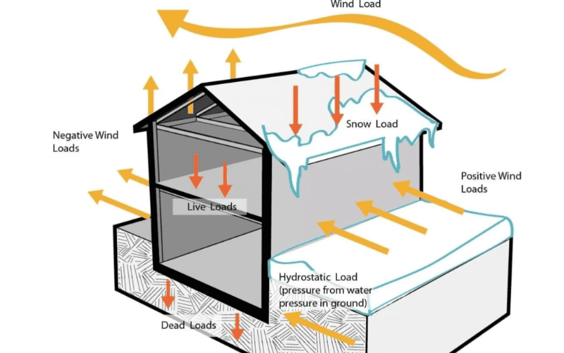
Types of Loads in Steel Structures
In steel structure design, load calculation is the key step that determines the safety, efficiency, and cost-effectiveness of a building. Different types of loads have different effects on the structure, so understanding their behavior is crucial for accurate PEB design.
At SteelPRO PEB, our engineers apply these load principles in the design of industrial warehouses, factories, and modular buildings across more than 30 countries.
Below is an overview of the most common load types used in steel structure design, with typical design parameters and global code references (GB50009, ASCE 7, Eurocode 3) to help guide safe and efficient calculations.
| Load Type | Typical Value Range (KN/m²) | Common Application |
| Dead Load | 0.10–0.20 | Roof + structural self-weight |
| Live Load | 0.30–0.50 | Roof or floor area |
| Wind Load | ≥0.30 | Industrial & high-rise PEBs |
| Snow Load | 0.20–1.00 | Cold or mountain regions |
| Crane Load | Variable | Heavy-duty industrial workshops |
1. Dead Load
The dead load encompasses the static weight of the rigid frame, as well as the weights of components such as the roof panel, purlins, insulation cotton, and others. Below are some typical dead load values:
- Purlin + roof panel (0.5mm thickness): 0.10 KN/m²
- Purlin + roof panel (0.5mm thickness) + roof lining board (0.5mm thickness): 0.15 KN/m²
- Purlin + sandwich panel: 0.15 KN/m²
The precise dead load calculation must be tailored to the specific circumstances. In cases where numerous hanging devices are installed on the roof, the weight of the beams used to connect and support these devices cannot be overlooked and should be incorporated into the roof’s dead load assessment.
2. Live load and roof hanging load
Roof live load: When using corrugated steel sheet light roof, the standard value of roof vertical live load should be 0.5KN/m2 (Note: When the rigid frame or purlin has only one variable and the load-bearing area exceeds 60m2, the live load for the steel frame can be 0.3KN/m2).
Roof hanging load: Including sprinklers, pipes, lamps, etc., roof hanging load can be included in the roof live load.
Commonly used roof suspension load values can be referred to as follows:
- Gypsum ceiling 0.15 KN/m2
- Air conditioning duct 0.05 KN/m2
- Lighting 0.05 KN/m2
- Sprinkler 0.15 KN/m2
It should be pointed out that since the light steel structure roof system is very light, when using design software such as STS (the software does not allow users to add suspension load conditions), it is more appropriate to merge the roof suspension core load into the live load. If the roof suspension load is considered in the dead load, the design is unsafe when the dead load + wind load combination is combined.
3. Snow load
When considering snow load, please note:
- It is necessary to consider μr—roof snow distribution coefficient according to Code 50009-2001. The basic snow pressure multiplied by the snow accumulation coefficient is the standard value of snow load;
- When designing the load-bearing components of the building structure and roof, the distribution of snow accumulation can be adopted according to the following provisions:
- Roof panels and purlins are adopted according to the most unfavorable situation of uneven snow distribution;
- Roof trusses and arch shells can be adopted according to the uniform distribution of snow accumulation in the entire span, the uneven distribution of snow accumulation, and the uniform distribution of snow accumulation in half a span respectively;
- Frames and columns can be adopted according to the uniform distribution of snow accumulation in the entire span.
4. Wind load
The wind load shape coefficient of the portal frame can be taken according to the “Building Structure Load Code” (GB50009-2001) or the “Technical Code for Lightweight Steel Structure of Portal Frame” (CECS102:2002). Please note the following:
- The basic wind pressure should be adopted according to the 50-year wind pressure given in Appendix D.4 of the load code, but it must not be less than 0.3kN/m2.
- Not all portal frames can be used according to CECS. The portal code is only applicable to: roof slope α≤10, average roof height ≤18m, house height-to-width ratio ≤1, and eaves height ≤the minimum horizontal size of the house;
- When the column foot is hinged and the l/h of the frame is less than 2.3 and the column foot is rigidly connected and the l/h is less than 3.0, it is safer to use the wind load body shape coefficient specified in GB50009 for frame design, while using the value of GB50009 in other cases will lead to unsafe design;
- In any case, the algebraic sum of the wall shape coefficients on both sides of the horizontal frame should not be less than 1.2.
5. Crane load
The vertical load of bridge (beam) crane or suspension crane should be taken according to the unfavorable position of the crane; The horizontal load can be ignored for manual crane and electric hoist.
6. Earthquake load
When the seismic fortification intensity is high and the building span is large, the height is high, or there are many sway columns in the width direction, the horizontal earthquake effect can be verified according to the “Building Seismic Design Code” under the rigid frame earthquake left and right combination. When calculating, the damping ratio can be taken as 0.05.
4. Other loads
7. Other loads
In addition to the common loads mentioned above, steel structures may also be affected by some special loads.
Thermal loads: Expansion and contraction of materials caused by temperature changes may cause stress in the structure. The effects of thermal loads can be mitigated by setting expansion joints or using flexible connectors.
Explosion load: The impact force generated by the explosion, usually used in the design of high-safety buildings.
Construction load: Temporary load generated during the construction process, such as construction equipment, material stacking, etc.
Vibration load: Load caused by mechanical equipment, traffic or other external vibration sources.
Corrosion load: Material performance degradation due to environmental corrosion, indirectly increasing the structural load.
In steel structure design, load analysis is a key step to ensure the safety and stability of the building. Whether it is dead load, live load, environmental load or other special loads, we will provide you with comprehensive analysis and design solutions. Should you have any inquiries regarding load analysis or design, please do not hesitate to reach out to us; we are committed to serving you with all our hearts!
Steel Structure Load combination
Why do we need a load combination?
In real-world steel construction, buildings are often subjected to multiple load effects acting simultaneously. Designing under a single load condition cannot reflect true behavior during operation.
At SteelPRO PEB, our engineering team performs load combination simulations using STAADPRO and Tekla, accurately modeling the interaction of dead, live, wind, and seismic loads to optimize both safety and material efficiency.
This practical approach ensures that each PEB structure design not only meets GB50009, ASCE 7, and Eurocode 3 standards but also achieves cost efficiency through refined combination ratios and safety factors.
Common load combinations
- Dead load + live load: This is the most common load combination, which is used to consider the static load and dynamic load of the structure under normal use conditions.
- Wind load + snow load: Commonly used in high-rise buildings or open-air facilities, considering the superposition of wind and snow weight.
- Earthquake load + dead load: In earthquake-prone areas, consider the stability of the structure under earthquake action and the combined effect of constant load.
Through integrated analysis, SteelPRO PEB’s system automatically evaluates multiple load cases to predict structural performance and identify the most economical and safe configuration — a crucial factor in large-span warehouses and industrial PEB projects.
The design of load combinations must follow local building codes (such as ASCE, European codes, etc.). These codes have formulated specific load combination requirements based on regional characteristics to ensure that the design is both safe and economical. Following the code can not only improve the safety of the structure, but also avoid overdesign and save costs.
Need professional help with your load combination or structural design?
Contact our certified engineers for a free consultation or request a sample PEB load combination report based on your project’s parameters.
Load Analysis and Design of Steel Structures
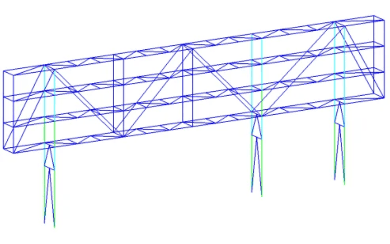
Finite Element Analysis (FEA)
Finite Element Analysis (FEA) is a core tool in SteelPRO PEB’s design workflow, allowing our engineers to simulate and visualize real-world stress distribution under combined loads — including dead, live, wind, and seismic forces. Using STAADPRO, Tekla, and ETABS, we generate precise models that identify stress points early, helping to reduce material waste and enhance the safety-to-cost ratio of every steel structure project.
Beam and column design
Beams and columns form the structural backbone of every steel building. At SteelPRO PEB, these components are designed with manufacturing precision in mind. Our structural models are directly converted into fabrication-ready drawings for CNC cutting and robotic welding in our ISO-certified plant. This ensures that each load-bearing member performs exactly as calculated, minimizing errors between design and on-site construction.
Load is transferred from beams to columns:
- The function of beams is to bear loads (such as the weight of the floor, the weight of people or furniture), and then transfer the loads to columns. Columns subsequently transmit the loads to the foundation. When designing, ensure that the load can be transferred smoothly to avoid structural imbalance.
Selection of beam and column size:
- The size of beams and columns should be determined according to the load size. If the size is too small, it may not provide adequate support, whereas if it is too large, it will result in material wastage. Engineers need to choose the right size based on the load and the code.
For example, a factory beam will need to support heavier equipment, so it needs to be larger or stronger steel, while a residential beam can be smaller.
Foundation Design
The foundation must transfer and balance loads efficiently with soil bearing capacity. SteelPRO PEB’s engineering team conducts soil and structural interaction assessments to ensure even settlement and durability. For complex soil conditions, we integrate pile or raft foundations within the design model, ensuring the full system — from steel frame to foundation — performs as one cohesive unit.
Load Transfer to the Ground:
- The foundation must be able to evenly distribute the load to the soil. When designing, consider the bearing capacity of the soil and make sure the foundation can support the weight of the entire structure.
Prevent Uneven Settlement:
- If different parts of the foundation sink at different rates, it can cause the house to tilt or even collapse. To mitigate this, engineers design the foundation considering soil conditions and load distribution. For example, in areas with soft soil, pile foundations can be used to transfer the load to deeper, more stable soil layers.
Through finite element analysis, proper beam and column design, and a solid foundation design, engineers can ensure that steel structures are safe and reliable in a variety of situations.
Every design delivered by SteelPRO PEB undergoes a complete internal review cycle — from FEA simulation to fabrication verification, ensuring that every load path is safe, manufacturable, and optimized for global building standards. Certified by ISO and CE, SteelPRO PEB bridges engineering design and industrial production, delivering efficient, durable, and factory-backed steel structures worldwide.
Challenges of Load Calculation for Steel Structures
Uncertainty of Load Estimation
Live and environmental loads such as wind, snow, and seismic effects fluctuate greatly in real-world projects, making accurate prediction difficult.
To address this, SteelPRO PEB’s engineers apply variable-load simulation and probabilistic safety factors, ensuring that every structure remains reliable even under the most unpredictable conditions.
Our design methodology is aligned with GB50009, ASCE 7, and Eurocode 3, providing a unified standard for global projects.
Complexity of Load Combinations
In complex projects, multiple load combinations — dead, live, wind, snow, and even seismic — may overlap and amplify each other.
SteelPRO PEB’s integrated design platform uses STAADPRO load combination matrices to test hundreds of possible interaction cases, automatically identifying the worst-case scenario for safe and economical design.
Software Limitations
Although software aids precision, human expertise and data accuracy remain decisive. SteelPRO PEB’s engineering workflow includes three-stage validation — design input check, simulation comparison, and fabrication verification — to eliminate calculation errors and guarantee data integrity throughout the project lifecycle.
How did we overcome these difficulties?
As a professional steel structure supplier, we are well aware of the challenges in load calculations.
At SteelPRO PEB, we combine advanced simulation software, decades of design expertise, and ISO-certified fabrication to deliver load calculations that are both accurate and buildable.
With over 1,000+ completed projects worldwide and 24 production lines producing up to 120,000 tons annually, our integrated approach ensures that each calculation directly informs real-world performance.
Every structure undergoes multi-round review — from model simulation to on-site verification — ensuring maximum safety, minimal waste, and verifiable reliability.
In addition, the team will review the data many times to ensure that every step is accurate, and ultimately provide customers with safe and economical steel structure solutions.
What is the difference between dead load and live load?
Dead load refers to the permanent weight of the structure itself, including beams, columns, and floor slabs, which remains constant. Live load, on the other hand, represents the variable weight that may change during use, such as the weight of people, furniture, and equipment. In simpler terms, dead load is the “fixed weight,” while live load is the “changing weight.”
How does wind load affect high-rise steel structure buildings?
The impact of wind load on high-rise buildings is mainly reflected in horizontal forces. Strong winds will produce pressure or suction on the surface of the building, which may cause the structure to shake or even deform. Therefore, wind loads must be specially considered when designing high-rise steel structures to ensure the stability and comfort of the building under strong winds.
How to calculate seismic loads on steel structures?
The calculation of seismic loads needs to take into account the seismic area, building weight, and structural design. The formula usually used is: seismic load = building weight × seismic acceleration × structural coefficient. The specific calculation must follow the local seismic design specifications to ensure the safety of the structure in an earthquake.