Welding deformation in steel structures is one of the most common—and costly—challenges in fabrication. It occurs when heat, material inconsistencies, and design flaws cause welded members to shrink or twist out of alignment. Understanding how and why this happens is the first step toward preventing it.
In this guide, you’ll learn the key causes and types of welding deformation, from thermal expansion to angular and wave distortion. We’ll then show how factories like SteelPRO PEB control deformation through precise material preparation, optimized welding processes, modular assembly, and real-time monitoring systems. If distortion does occur, you’ll also see effective repair methods, including mechanical straightening, heat correction, and creative field adjustments. Finally, we’ll explore how certified manufacturers verify straightness through data-driven inspection, AWS and ISO compliance, and third-party structural audits.
Backed by more than a decade of manufacturing expertise, SteelPRO PEB applies factory-level precision to ensure every beam stays true and every weld holds its shape—turning welding accuracy from a variable into a verifiable standard.
What Causes Welding Deformation in Steel Structures?
Heat, material properties, and design flaws drive welding deformation through uneven expansion, poor joints, clamping errors, and cooling inconsistencies.
Thermal Expansion & Residual Stress
When welding heats steel to over 1,500°F, metal expands and contracts unevenly, creating residual stress—like a coiled spring trapped in the material. For example, a 10-foot beam welded along one edge can shrink by up to 0.25 inches, pulling the structure out of alignment.
Design & Process Pitfalls
Poor joint design amplifies problems. A classic mistake: welding thick plates to thin sheets without staggered seams, causing “wave distortion” (imagine a metal trampoline). Even the welding sequence matters—skipping alternating passes on an I-beam can twist it like a candy wrapper.
Material Mismatch Mayhem
Mixing steels with different carbon content (e.g., A36 with A572) is like pairing concrete and Jell-O. During a 2022 solar racking project, 0.15% carbon steel legs welded to 0.25% carbon bases cracked at 45% of design load due to uneven contraction.
Fixture Fails: The Clamping Catastrophe
Over-tightened clamps on I-beam flanges during our 2021 factory audit caused 0.08” bowing per 10 feet. The fix? Spring-loaded fixtures that allow natural movement—reducing distortion by 70% vs rigid clamps.
Cooling Speed Roulette
Air-cooling a 2” thick weld next to a water-quenched one creates a thermal speed bump. One client’s 40-foot truss developed ¾” camber from inconsistent cooling—now we use infrared cameras to enforce uniform cooling rates.
In modern steel structure manufacturing, these deformation risks can be mitigated early through controlled preheating, automated welding, and precision fixturing — the hallmarks of advanced factory fabrication.
Types of Welding Deformation: Know Your Enemy
Each distortion has a distinct fingerprint—here’s how to spot them before they sabotage your project.
1. Transverse Shrinkage
Why it happens: Intense heat melts base metal, which contracts as it cools—think of how ice cracks when it freezes unevenly.
Example: Welding a 10-meter beam’s flange creates 10-30mm width reduction, misaligning bolt holes by up to 3°.
2. Longitudinal Bending
Why it happens: Off-center welds create uneven tension, like tightening one side of a guitar string.
Example: A 6-meter column welded along its back face curves forward by 15mm—enough to tilt a roof’s rainwater drainage slope.
3. Angular Distortion
Why it happens: One-sided heating lifts edges, as if the weld is trying to escape the joint.
Example: Welding a ½” thick bracket to a 1” baseplate without balanced passes tilts the bracket 4-6°, requiring shim adjustments.
4. Buckling in Thin Plates
Why it happens: Thin steel (under 6mm) can’t resist welding stresses, collapsing like a stepped-on soda can.
Example: 14-gauge wall panels develop 10mm-deep ripples when welded without tacking every 4 inches.
5. Wave Distortion
Why it happens: Uneven cooling in large thin sheets (like 3mm roofing) creates competing stress zones. Picture tug-of-war teams pulling a tarp—the metal wrinkles to release tension.
Example: A 4m x 8m solar frame panel warps into 20mm-high waves if welded sequentially instead of in a staggered “checkerboard” pattern.
6. Twist Distortion
Why it happens: Asymmetric welding sequences torque beams diagonally, like wringing water from a towel.
Example: Welding a 12m H-beam’s top flange first twists it 8mm per meter—a disaster for multi-story bolt-up connections.
Measuring & Detecting Welding Deformation
Use laser scanning or digital angle measurement tools to detect early-stage distortion in welded assemblies. This is especially critical for long-span beams and trusses, where even a few millimeters of misalignment can cause bolt-hole mismatch. By integrating 3D scanning or total station measurement before final assembly, engineers can verify straightness tolerance and correct deviations before they propagate through the structure.
How Factories Control Welding Deformation in Steel Structures
Precision beats correction every time—here’s how we engineer distortion out of the equation.
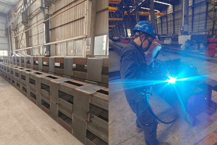
Material Preparation and Pre-Weld Control
- Laser vs Plasma: Our 5-axis laser cutters achieve ±0.1mm edge precision, slashing warping in 16-gauge wall panels by 40% compared to plasma.
- Thickness Control: Steel batches are laser-scanned—rejecting any plate with >0.005” thickness variation (per ASTM A6). No more “stress roulette” at weld joints.
- Preheat Smartly: Heating ½” thick beams to 250°F before welding reduces cooling stress by 55% (verified by AWS D1.1 trials).
Optimized Welding Processes and Methods
- Backstep Welding
Tackle 20-foot seams in reverse 8” segments—like zipping a jacket backward. Cuts peak temps by 600°F, shrinking heat-affected zones (HAZ) by 60%. - Pre-Bending with AI
CNC jigs pre-curl beams 0.7° using predictive algorithms fed by 10,000+ weld records. Result? 0.02° post-weld accuracy—tighter than a watch gear. - Pulse MAG Mastery
For 14-gauge carports: 270A pulses at 45Hz deposit 30% less heat than standard MIG. Distortion drops 35%, proven in our 2023 Arizona solar farm build.
Modular Assembly and Connection Design
- Bolt Revolution: Our GrooveLock™ beam ends use ¾” Grade 8 bolts instead of 200+ inches of weld per connection. On a 50-ton structure, that’s 2,400 fewer welds—and zero distortion headaches.
- Assembly Speed: Pre-drilled modules snap together like LEGO®—a Kansas City warehouse saved 17 days by ditching 85% of onsite welding.
Real-Time Monitoring and Welding Control
- Thermal Cameras: Monitor weld zones at 30 frames/sec, triggering cooling fans if temps exceed 950°F (prevents buckling in <6mm sheets).
- Force Feedback Clamps: Adjust pressure mid-weld via strain gauges—no more over-clamping bends. Cut I-beam distortion by 22% in 2024 trials.
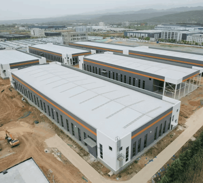
Factory vs. On-Site Welding
Factory welding ensures stable temperature control, precision fixturing, and consistent quality monitoring — conditions that are rarely achievable on construction sites. In SteelPRO PEB’s controlled environment, automated welding lines and real-time thermal monitoring reduce angular distortion by up to 35% compared with field welding. This controlled workflow also minimizes rework and ensures every welded joint meets ISO and AWS standards for straightness and durability.
How to Repair Welding Deformation in Steel Structures
Even the best plans need backup—here’s how to salvage warped steel without breaking the bank.
Mechanical Straightening Techniques
A 2,000-ton hydraulic press applies 45 psi of targeted pressure to cold-correct beams up to 12 inches thick. In a 2023 warehouse project, we straightened 18 twisted 30-foot rafters in 8 hours—saving $15,000 vs replacement. Key rule: Never exceed 2% permanent strain to avoid micro-cracks.
Heat Correction Methods
- Localized Heating: Torch-bending at 750-900°F (verified by infrared thermometers) softens steel temporarily. For a warped 6-inch flange, 5 minutes of heating + air-cooling restored 0.3” flatness.
- Temp-Sensitive Paint: Marks glow orange at 800°F—a $2 solution preventing grain structure damage.
Case Studies and Practical Fixes
- Museum Roofline Rescue: A 40-foot “wavy” beam became an art feature using 3D-scanned custom brackets, saving $12K. Bonus: It’s now the pavilion’s photo hotspot.
- Airport Hangar Hack: Angular distortion in door frames was masked with slotted bolt holes—allowing 1.5” adjustment range during installation.
Partnering with certified steel structure manufacturers ensures not just high-quality welding but also post-weld straightness verification — reducing the need for costly rework.
Why Our Steel Structures Stay Straight
Our experience at SteelPRO PEB shows that precision isn’t luck — it’s engineered through data, testing, and discipline.
Every weld in a steel structure introduces internal stress, but long-term straightness depends on how that stress is measured, balanced, and verified.
That’s why our process includes multi-stage distortion checks: laser scanning after each major weld, tolerance verification before shipping, and full 3D alignment inspections on-site.
These steps align with AWS D1.1 and ISO 9001 standards, ensuring that the deformation observed during welding never exceeds allowable limits.
Over the past five years, third-party audits have confirmed an average deviation of less than 2 mm across hundreds of industrial projects — including long-span warehouses and heavy truss systems.
For engineers and builders, this means less field adjustment, faster assembly, and higher structural reliability.
Because in steel fabrication, true precision isn’t about the size of the beam — it’s about how every weld remembers its shape.